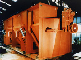
The washer compartments are provided with slot-perforated sheet steel screen bottoms. Manholes are provided laterally below the screens and washing tank bottom is provided with mud discharging pockets and valves.
The stone catcher compartments are furnished with floor gratings inclined towards the stone locks. The stone locks are equipped with the inside and outside slide gates operated pneumatically and interlocked against simultaneous opening, with one mud discharge device each, and With a manhole holder the floor grating in the lateral part of the trough section.
The air cylinders for the slide gates of the stone locks are ventilated manually. Just as in the washing compartments, the pneumatic actuation if controlled automatically through an electrical switch mechanism from a program of opening and closing times governed by the washing conditions.
The stones are eliminated while the beet washer is operating. Once special circulation pump each for the two stone locks enables the stones to be eliminated with almost no beets being lost. The stones can then be removed from a grating installed in front of the stone locks. The pump and flushing line is operated by means of quick-acting gate valves.
The circulation pump device include two pumps each with the following specification:
Drive power each 15 HP
Motor speed 1,800 rpm
Voltage 460 V
Frequency 60 cps
Delivery 1,300 gpm
Total head 7 ft. W. C.
Included also are circulation lines and a fully automatic control unit for operation of the stone locks.
The mud discharge pockets are located in the tank bottom and equipped with special valves which are pneumatically operated on a sequential and timed basis by the included controller.
The ejector compartment is located at the discharge of the washer together with the last
stone catcher compartment. The beets are ejected from the beet washer longitudinally or to the side by ejector arms mounted on the shaft. (Please specify which is required.)
The anti-spray mount serves for screening off the spray water caused by the rotation
of the washer shaft. The mount is composed of separate bolted sheet metal parts screwed to the washer tank.
The washer shaft is a hollow shaft doing the actual washing work. It is provided with steel washing paddles and with bolted throw-over and ejector flights. The shaft is sealed in the end plates of the washing tank by glands flushed with fresh water. The washer shaft is supported by two self-aligning roller bearings, a fixed bearing for absorbing the axial shaft thrust and one loose bearing, both of them mounted as external bearings on brackets secured to the trough end plates.
The drive consists of a stub shaft bolted to the washer shaft and driven by a shaft mounted gear with flanged three-phase motor. A staring and safety coupling is provided between motor and gearing.
The service platform as well as the discharge chute are to be provided by the customer. If requested they can be included at additional cost.